 English


Views: 0 Author: Site Editor Publish Time: 2026-08-06 Origin: Site


To choose your LED spotlights effectively, evaluate total luminous flux (lumens) against target illuminance (lux), select appropriate Correlated Color Temperature (CCT) and Color Rendering Index (CRI/TLCI), calculate beam angles based on mounting distance and throw ratio, verify ingress protection ratings for the operating environment, and ensure rigorous dimming protocol compatibility (DMX512, RDM, or Triac).
The 5 essential criteria for choosing your LED spotlights
Luminous power and luminous flux
Color temperature
Lighting angle
Protection rating (IP)
Compatibility with dimmers
What LED spotlight power should you choose to light the ceiling?
3 mistakes to avoid when choosing your LED spotlights

Selecting directional LED fixtures requires a comprehensive technical evaluation of electrical power consumption, photometric output, chromatic accuracy, optical beam dispersion, environmental ingress protection, and control gear interface protocols.
Engineering robust illumination systems demands shifting focus from legacy incandescent wattage metrics to modern photometric parameters. A solid-state spot light operates as an integrated opto-electronic system where chip-on-board (COB) architecture, driver efficiency, and secondary optics govern real-world performance. When configuring commercial, architectural, or studio environments, evaluating electrical wattage in isolation leads to inaccurate light levels. Technical buyers must analyze optical delivery efficiency, measured in delivered lumens per watt, alongside thermal dissipation capabilities. To thoroughly understand the fundamental photometrics and internal optics driving modern solid-state fixtures, engineers regularly consult comprehensive guides on how spotlights work in professional lighting systems.
Industrial client feedback across European markets indicates a strong preference for modular designs that separate the LED light engine from driver electronics. This architectural separation drastically reduces total cost of ownership by allowing driver upgrades or field servicing without dismounting complex optical housings. Furthermore, understanding the interaction between raw chip emission and optical reflectors or total internal reflection (TIR) lenses ensures that target surfaces receive precise illuminance without unwanted spill light. Professional specification relies on rigorous photometric data files, such as IES or LDT files, to simulate beam propagation accurately prior to hardware installation.
To establish baseline criteria for selecting high-performance directional fixtures, technical teams must evaluate the core opto-electronic parameters that define system quality and long-term operating stability.
Luminous flux, measured in lumens (lm), defines the total quantity of visible light emitted by an LED engine, whereas luminous power (or electrical power, measured in watts) indicates the energy consumed by the system. In modern solid-state fixtures, the ratio of luminous flux to electrical power yields luminous efficacy (lm/W), which represents the primary benchmark for energy efficiency. Evaluating a high-output spot light demands precise measurement of useful lumens within the intended beam angle, rather than raw emitter flux prior to optical transmission losses.
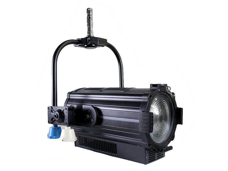
In high-density studio and architectural installations, optical loss through secondary lenses, Fresnel elements, and beam-shaping shutters can reduce total delivered lumens by 15% to 30%. Therefore, system design requires evaluating optical system efficiency alongside driver efficiency. European broadcast clients frequently specify high-power COB arrays operating at reduced drive currents to maximize efficacy and lower thermal junction stress. To maintain pristine optical clarity, professional studio installations utilize specialized fixtures such as a high-CRI 200W LED Fresnel spotlight for broadcast applications, which pairs substantial luminous flux with soft-edge beam control.
Below is a comparative breakdown of photometric and electrical metrics across standard directional LED light engines:
LED Engine Power (W) | Raw Luminous Flux (lm) | Effective Efficacy (lm/W) | Typical Target Application | Recommended Mounting Height |
50W COB | 5,000 - 6,000 | 100 - 120 | Accent & Retail Track Lighting | 2.5m - 3.5m |
100W COB | 10,000 - 12,000 | 100 - 120 | Low-Ceiling Studio & Gallery Key Light | 3.5m - 5.0m |
200W COB | 20,000 - 24,000 | 100 - 120 | Broadcast Studio & Theater Key Light | 5.0m - 8.0m |
300W COB | 30,000 - 36,000 | 100 - 120 | High-Bay Architectural & Stage Spotting | 8.0m - 12.0m |
Color temperature, expressed in Kelvin (K), defines the spectral energy distribution and visual warmth or coolness of emitted white light along the Planckian locus. Correlated Color Temperature (CCT) selection directly impacts visual acuity, ambient atmosphere, and camera sensor rendering in broadcast environments. Standard CCT benchmarks include warm white (2700K–3000K), neutral white (4000K–4500K), and daylight balanced (5600K–6500K).
In professional broadcast and theater environments, spectral fidelity extends beyond CCT to encompass the Color Rendering Index (CRI, Ra) and the Television Lighting Consistency Index (TLCI). Modern high-grade fixtures achieve CRI and TLCI ratings exceeding 95, ensuring accurate color rendering across skin tones and fabric textures. Advanced optical designs frequently utilize tunable white engines or multi-channel LED arrays (RGBW/CW-WW) to allow dynamic CCT adjustments while preserving spectral continuity across the Planckian curve. Detailed optical mechanics regarding spectral power distribution are thoroughly discussed in our overview of optical system design in LED spotlights.
Why do optical engineers prioritize high CRI/TLCI over maximum raw lumen output? In precision environments like broadcast studios and museum galleries, color fidelity takes precedence over marginal efficacy gains. A high-efficiency spot light that skews spectral output with excessive green spikes forces post-production color correction and ruins set aesthetics. European clients overwhelmingly demand MacAdam Ellipse 3-step or 2-step color binning to guarantee absolute color uniformity across multi-fixture installations.
The lighting angle, or beam angle, is defined by the full width at half maximum (FWHM) intensity point, representing the angle at which light intensity drops to 50% of the peak center beam intensity (CBCP). Beam angle selection governs spatial light distribution, throw distance, and the edge definition of the projected light pool. Angles typically range from narrow spot (10°–18°), medium flood (24°–36°), to wide flood (45°–60°+).
Calculating the required beam angle involves evaluating mounting height, throw distance, and target footprint area. Secondary optics, such as optical grade PMMA TIR lenses, aluminum parabolic reflectors, or glass Fresnel lenses, shape the raw Lambertian emission of the LED emitter into precise beam profiles. In professional stage and studio environments, adjustable zoom systems allow continuous beam angle tuning without changing physical fixtures. Incorporating an adjustable glass Fresnel lens in a high-power 200W LED Fresnel spot light provides variable beam shaping from a tight 15° beam to a broad 50° flood.
The table below summarizes standard optical beam angles and their calculated throw field dimensions:
Beam Category | FWHM Angle (°) | Beam Diameter at 5m (m) | Beam Diameter at 10m (m) | Primary Application Profile |
Narrow Spot | 10° - 15° | 0.87 - 1.31 | 1.75 - 2.63 | Long-throw architectural highlight & stage soloing |
Medium Spot/Flood | 24° - 30° | 2.13 - 2.68 | 4.25 - 5.36 | Commercial display, gallery framing, key lighting |
Wide Flood | 45° - 60° | 4.14 - 5.77 | 8.28 - 11.55 | General wash, studio background, space fill |
The Ingress Protection (IP) rating, standardized under IEC 60529, defines the degree of environmental sealing provided by a fixture enclosure against solid particles and liquids. The rating consists of two digits: the first digit (0–6) indicates solid ingress protection, while the second digit (0–9) measures liquid ingress protection. Selecting the correct IP rating prevents internal optical degradation, driver short-circuiting, and premature LED degradation.
Indoor installations, such as climate-controlled broadcast studios, theaters, and retail venues, typically utilize IP20-rated fixtures. These enclosures focus on optimized airflow for passive or low-noise active cooling systems. Outdoor architectural applications, humid environments, or touring rigs demand IP65 or IP66 sealed housings utilizing die-cast aluminum enclosures, waterproof GORE breather valves, and silicone gaskets. Understanding environmental protection requirements is a key consideration detailed in the analytical breakdown of heavy-duty spotlight construction standards.
Clients in harsh operational environments frequently inquire why waterproof IP65 units are heavier than indoor units. Die-cast outdoor housing structures must incorporate integrated heat-pipe fins, sealed cable glands, and thickened glass optics to maintain structural integrity under thermal expansion and ambient weather pressure changes. Choosing an under-rated enclosure for high-humidity environments leads to internal lens condensation, rapid corrosion of driver circuitry, and catastrophic optical array failure.
Dimming performance defines the professional viability of a directional LED system. Unlike incandescent filaments that scale voltage smoothly, LED drivers require sophisticated modulation techniques—primarily Pulse-Width Modulation (PWM) or Analog Constant Current Reduction (CCR)—to adjust lumen output. Protocol compatibility must be established across control infrastructures, including DMX512-A, Remote Device Management (RDM), DALI, 0-10V, or Phase-Cut (Triac/ELV) systems.
Broadcast and theatrical settings demand flicker-free dimming across high-speed camera frame rates. PWM frequencies exceeding 15,000 Hz or high-resolution 16-bit dimming curves (yielding 65,536 discrete intensity steps) prevent visible banding or stepping during slow dimming transitions. For television studios, utilizing a studio-grade 200W LED Fresnel spotlight with high-frequency DMX control ensures seamless integration with automated lighting consoles and camera shutter speeds.
To assist system engineers in selecting compatible dimming control gear, the matrix below highlights key protocol characteristics:
Control Protocol | Signal Type | Resolution / Steps | Primary Application Field | Flicker Vulnerability |
DMX512-A / RDM | Digital RS-485 | 8-bit (256) / 16-bit (65,536) | Stage, Broadcast Studio, Architectural | Zero (at high PWM rates) |
DALI / DALI-2 | Digital Bus | 8-bit logarithmic | Commercial Buildings, Smart Offices | Low to Zero |
0-10V / 1-10V | Analog Voltage | Continuous Analog | Industrial High-Bay, Office Track | Medium (Driver Dependent) |
Triac / Phase-Cut | AC Phase Modulation | Variable Analog | Retrofit Residential & Hospitality | High (Requires Snubber Circuits) |
Maintenance & Thermal Management Tip: Always conduct periodic checks on LED driver thermal pad interface and cooling fan heat sinks. Over time, dust accumulation on aluminum cooling fins increases junction temperature ($T_j$), which accelerates lumen depreciation (L70/B10 lifespan reduction) and causes chromaticity shift. Maintaining junction temperatures below 85°C preserves color consistency and operational lifespan.
To illuminate a ceiling effectively using indirect uplighting or recessed accent spot fixtures, select an LED spotlight power output based on target ceiling height, surface reflectance factor, and required ambient lux levels, typically ranging from 15 to 30 watts per square meter of target surface area.
Indirect ceiling lighting relies on treating the ceiling plane as a secondary diffuse reflector. When projecting light upward, the total efficiency of the system is governed by the Inverse-Square Law and the directional reflectance coefficient ($\rho$) of the ceiling material. Smooth white plaster features a high reflectance factor ($\rho \approx 0.75–0.85$), whereas textured, wooden, or dark industrial concrete ceilings absorb significant photometric energy ($\rho \approx 0.20–0.45$). Selecting an underpowered directional engine results in muddy visual ambient levels, while overly intense narrow beams create hot spots that ruin spatial balance. Technical parameters for calculating indirect lighting parameters can be referenced in our practical study on indirect optical illumination principles.
In high-ceiling architectural projects (ranging from 4 to 8 meters), engineering teams utilize narrow to medium beam optical lenses (24° to 36°) to throw light to the ceiling plane without excessive wall spill. Calculating the necessary luminous flux requires applying the Lumen Method formula adapted for indirect reflection:
$$E = \frac{\Phi_{\text{total}} \times \text{UF} \times \text{MF}}{A}$$
Where $E$ represents target illuminance (lux), $\Phi_{\text{total}}$ is total lamp lumens, $\text{UF}$ is Utilization Factor (accounting for ceiling reflectance and room cavity ratio), $\text{MF}$ is Maintenance Factor (typically 0.8 for clean indoor spaces), and $A$ is floor area ($\text{m}^2$). For standard commercial spaces requiring 200 lux of indirect ambient illumination on a white ceiling at a 4-meter mounting distance, a solid-state spot light array delivering 3,000 to 5,000 lumens per fixture channel ensures uniform light coverage without glare.
Practical steps for selecting ceiling illumination power profiles include:
Measure structural clearance and calculate ceiling reflectance based on paint finish and material composition.
Determine required target lux levels (e.g., 100–150 lux for ambient relaxation, 300+ lux for task-oriented commercial spaces).
Calculate total required lumens incorporating room cavity ratios and optical reflection losses.
Select fixture wattage matching lumen requirements based on the light engine's native efficacy (lm/W).
Space fixtures uniformly to ensure beam overlaps occur at the 50% beam intensity threshold, eliminating spatial shadowing.
The three primary mistakes in LED spotlight procurement are ignoring thermal dissipation and junction temperature limits, selecting incorrect optical beam angles for target distances, and failing to verify driver-control protocol impedance compatibility.
Ignoring Thermal Dissipation Architecture and Emitter Junction Temperatures: The most frequent failure mode in high-output LED installations stems from evaluating raw lumen output while neglecting heat sink engineering. LED chips convert approximately 30% to 40% of electrical energy into visible light, while the remaining 60% to 70% is converted into heat. If the heat sink fails to conduct thermal energy away from the COB substrate, the junction temperature ($T_j$) spikes rapidly. Excessive junction temperature causes immediate chromaticity shift, accelerated lumen depreciation, and premature bond-wire failure. Professional technical buyers must verify heat sink material (e.g., cold-forged 1070 aluminum or pure copper heat pipes) and thermal resistance parameters (°C/W) rather than relying solely on driver wattage ratings. Further details on thermal management engineering are detailed in our analysis of thermal dissipation in high-density LED spotlights.
Mismatching Optical Beam Dispersion with Target Throw Distances: Installing a wide flood fixture for a long-throw accent application, or using a tight spot fixture for low-clearance ambient washing, severely degrades lighting quality. A narrow 10° spot light deployed at a short 2-meter mounting distance creates harsh center intensity with extreme light falloff, causing severe glare and visual fatigue. Conversely, using a 60° wide fixture at an 8-meter height spreads photometric energy too thin, failing to achieve target lux requirements. Optical planning requires verifying Center Beam Candlepower (CBCP) curves and calculating beam footprint dimensions at specific throw distances prior to hardware specification.
Overlooking Control Gear Compatibility and Driver Harmonic Distortion: Selecting fixtures without verifying driver impedance, control interface protocols, and Total Harmonic Distortion (THD) creates operational instability. Connecting non-isolated phase-cut dimmable drivers to advanced DMX control systems leads to audible driver buzzing, light flicker under high-speed cameras, and erratic dimming curves below 10% output. In industrial installations, drivers with high THD (>20%) and low Power Factor (<0.9) inject electrical noise into facility power lines, tripping circuit breakers and overheating neutral conductors. Specifying industrial-grade isolated drivers with active Power Factor Correction (PFC $\ge 0.95$) and high-frequency PWM output guarantees stable, flicker-free operation across all intensity levels.
Selecting professional LED spotlights requires a rigorous engineering approach that balances photometric output, optical precision, thermal management, and control system architecture. By carefully evaluating luminous efficacy, spectral quality (CRI/TLCI), precise beam angles, ingress protection, and flicker-free dimming protocols, technical specifiers can design reliable lighting systems tailored to commercial, broadcast, and architectural applications. Avoiding common pitfalls—such as neglected thermal dissipation, miscalculated optical throw ratios, and driver incompatibility—ensures long-term operational performance and maximum return on investment.